Blackmagic Design ATEM Television Studio HD
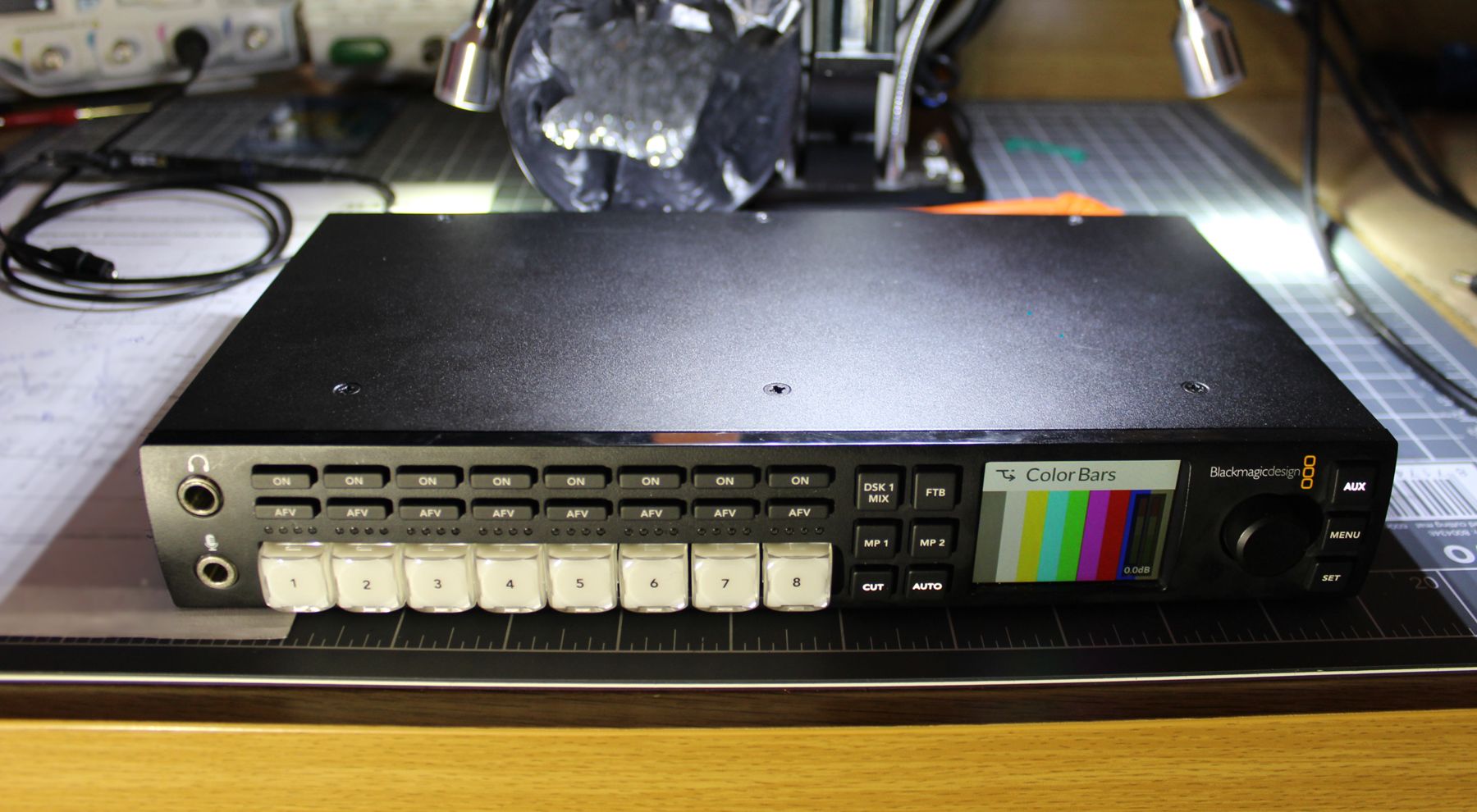
Another bit of professional video kit in need of repair, this ATEM Television Studio HD had faulty SDI outputs. 4 In total!
- SDI Output 5
- SDI Output 6
- Program
- Aux
Needless to say with your main PGM and AUX outputs dead a switcher is not much use.
Even before opening this switcher up I suspected the SDI cable drivers on the outputs had failed, at this point I have replaced these driver ICs in a variety of equipment. A quick way for me to check this is to use the oscilloscope to probe the input to the cable driver. Additionally, one of the output pins of the cable driver will often go short to ground or VCC.
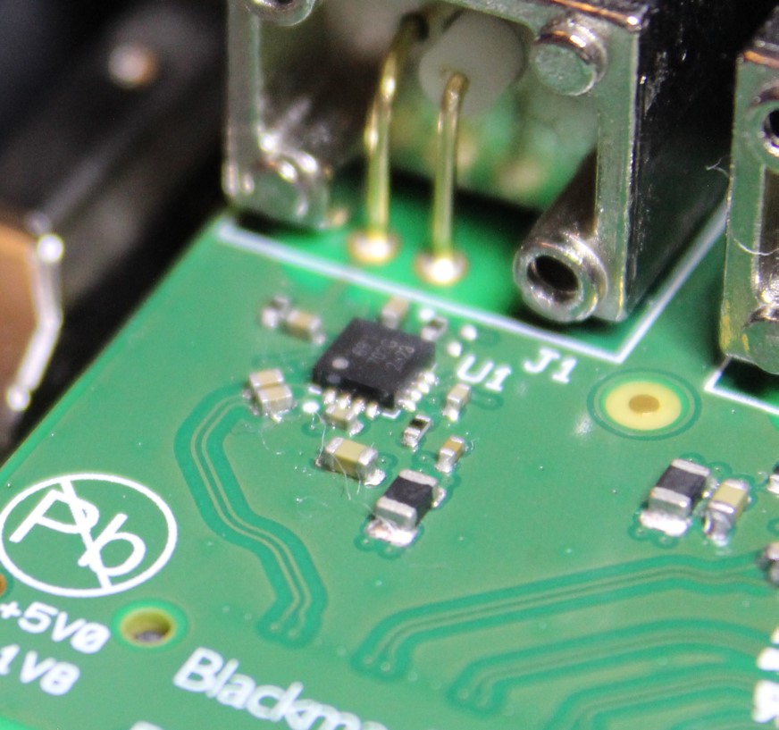 SDI Cable Driver - "2823"
In this case each of the cable drivers were showing a signal hitting the cable driver input pins but no output at all. Good reason to suspect the IC had failed.
To cover all bases, I measured voltage rails around the IC and everything measured correctly. Time to order some replacements.
All I had to go off was the number “2823”. After much searching I found a series of SDI Cable drivers made by “Macom” which at the very least matched the package (3x3mm, 16-pin MLF)
I was able to get the possible list down to 3 part numbers:
- Macom M21428
- Macom M22428
- Macom M23428
As the datasheet for the M21428 was available I started comparing the datasheet pinout to the PCB and things didn’t quite match. The datasheets for the M22428 and M23428 are not available and I have been unable to obtain them.
I did find a pin compatibility guide comparing the M21428 to the M22428 & M23428 and the changes made sense with the Atem’s PCB. As the M22428 was not available I decided to take a chance on the M23428.
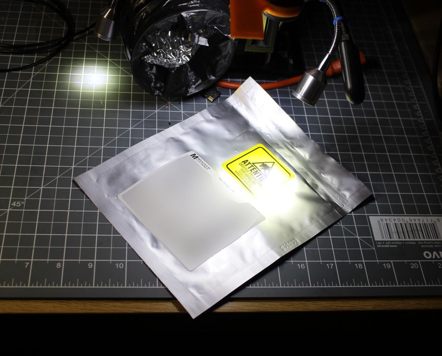 Delivery Time!
The M23428G-33 SDI Cable Drivers had arrived, unfortunately the markings showed “2833” whereas the ICs on the ATEM board are marked with “2823”. Without the datasheets it is hard to confirm exactly what the differences are but I believe the “2823” will be the M22428 and the two are pin compatible. The M23428 supporting higher data rates.
Replacement was simply a case of using hot air to remove the old IC…
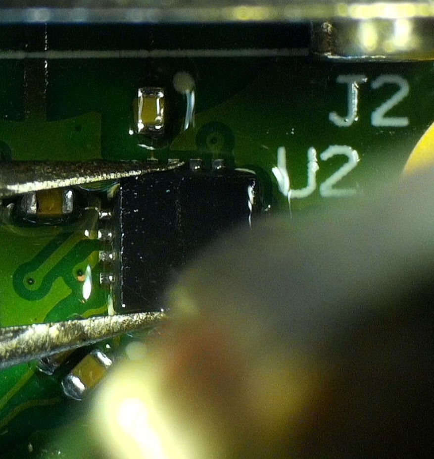
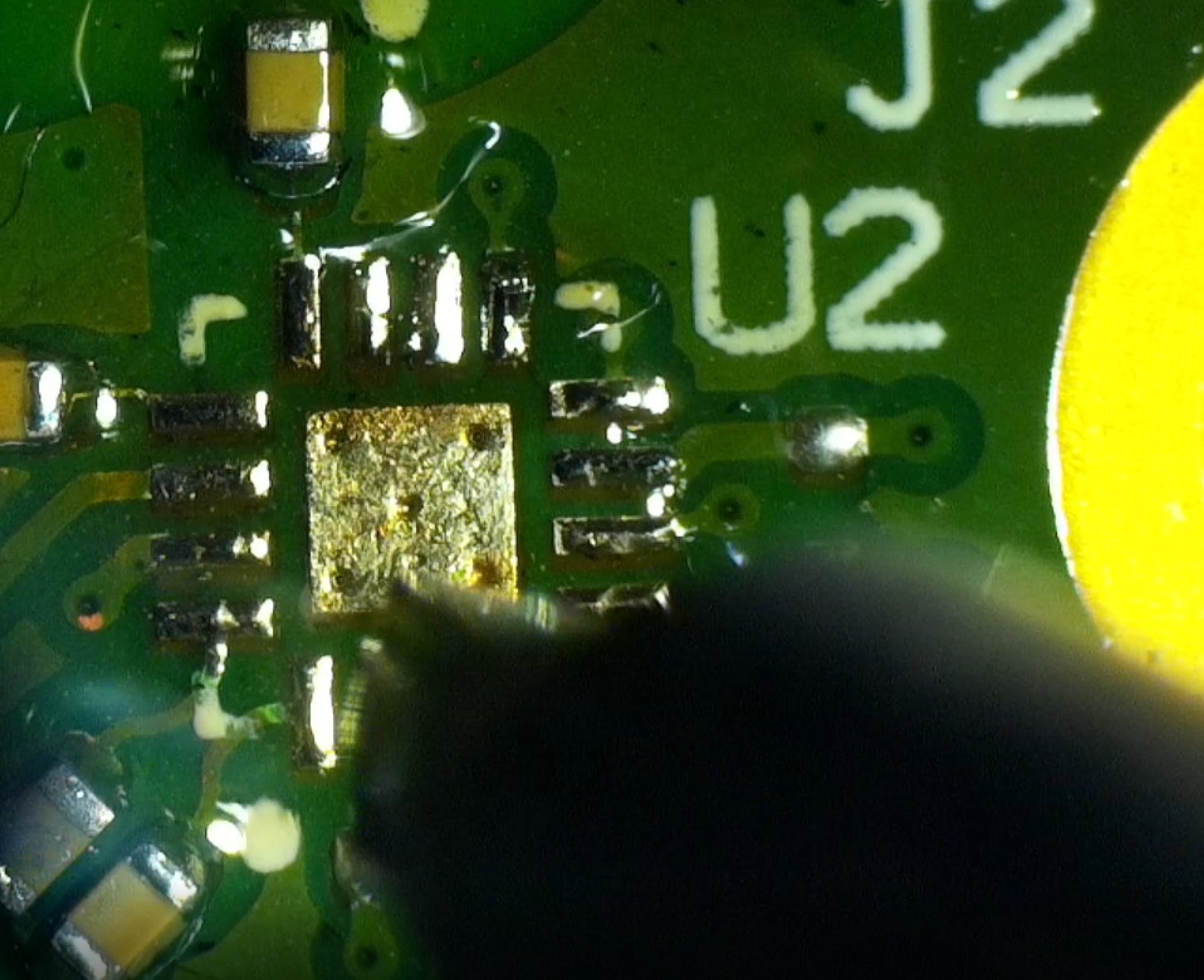
…Cleaning up the pads…
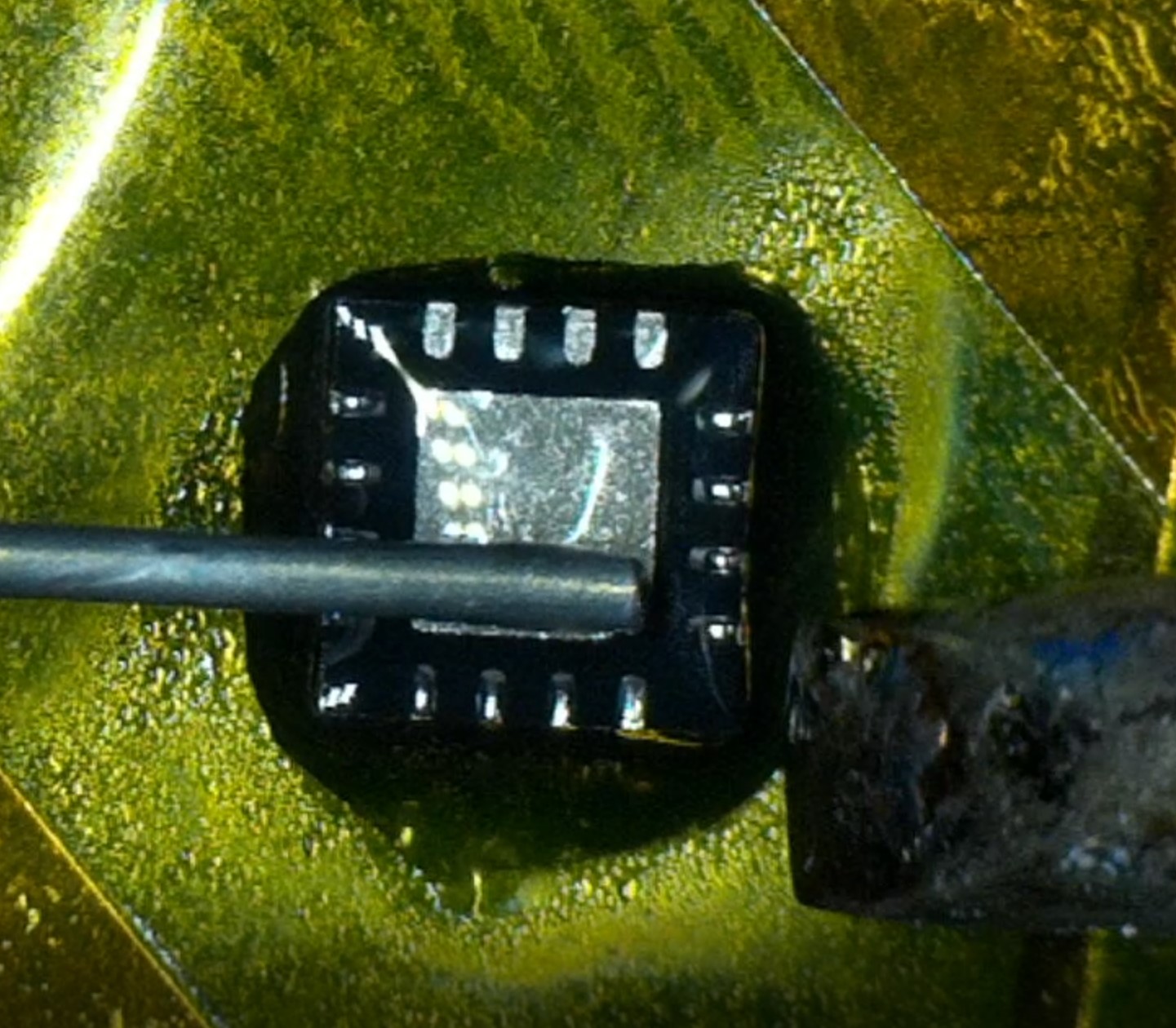
…Preparing the new IC, I like to tin the “pins”. I find it helps with alignment.
And Finally, reflowing the new IC in place.
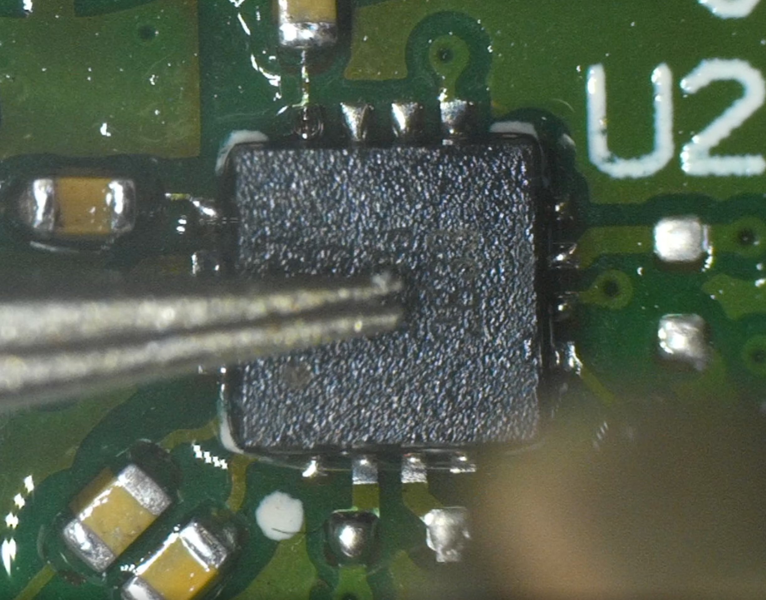
A bit of cleanup with some alcohol, visual inspection, and a quick test for power supply rail shorts or anything else that could cause immediate damage and it was time for a test…
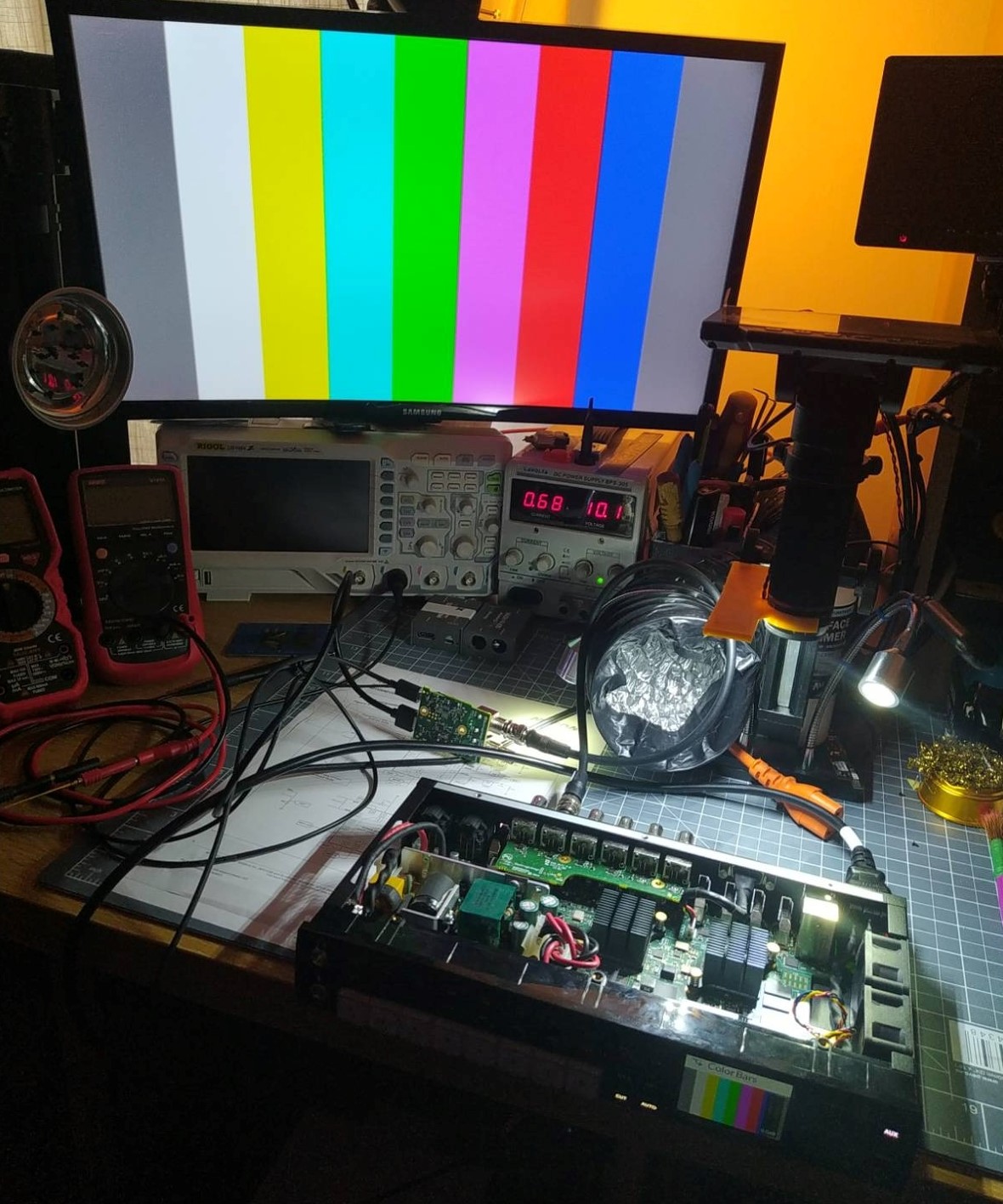 Success!
It works! Now to repeat the process for the remaining outputs. 😁